Detailed Explanation of the Working Principle and Application of YXC Series Electrical Contact Pressure Gauges
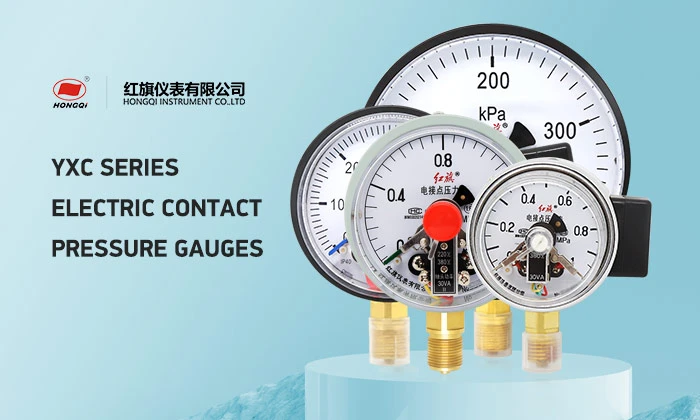
The YXC series electrical contact pressure gauge is a special type of pressure gauge that integrates electrical signal output functions on the basis of a common spring-tube pressure gauge. Its core value lies in its ability to not only display pressure values in real time but also trigger switch signals (such as alarms or start/stop equipment) through an internal contact mechanism when the pressure reaches a preset threshold, achieving dual functions of "monitoring + automatic control". It is widely used in industrial production scenarios where pressure needs to be safely monitored or automatically regulated.
I. Core Working Principle: "Mechanical Pressure Measurement + Contact On/Off" Synergy
The working principle of the YXC series electrical contact pressure gauge is divided into two core parts: pressure measurement and display, and electrical signal triggering. The specific process is as follows:
1. Basic Pressure Measurement and Display (Same as Common Spring-Tube Pressure Gauges)
This is the prerequisite for electrical signal control and adopts a mature spring-tube pressure measurement structure:
Step 1: Pressure Transmission: The measured medium (gas or liquid) enters the internal "spring tube" (the core elastic element, usually made of copper alloy or stainless steel) through the instrument interface. The spring tube undergoes elastic deformation due to internal pressure changes (it extends outward when pressure increases and contracts when pressure decreases).
Step 2: Mechanical Transmission: The deformation of the spring tube is transmitted to the movement (a transmission mechanism composed of sector gears and center gears) through a connecting rod, converting the linear displacement at the tube end into the rotational movement of the center gear.
Step 3: Pointer Display: The center gear is fixedly connected to the pointer shaft. The rotation of the gear drives the pointer to rotate synchronously, and the pointer indicates the current pressure value on the dial, achieving the conversion of "pressure → mechanical deformation → pointer reading".
2. Core: Electrical Signal Triggering (Contact On/Off Control)
This is the key difference between the YXC series and common pressure gauges. It achieves pressure threshold control through an internal contact component. The core structure includes "upper limit contact", "lower limit contact", and "common contact" (a three-contact design is mainstream, while some simple models have two contacts):
Contact Component Structure:
Common Contact (Common Contact, C): Fixed on the pointer shaft and rotates synchronously with the pointer, acting as a "movable electrode".
Upper Limit Contact (Upper Limit Contact, H): Fixed at the preset "high pressure threshold" position on the inside of the dial (for example, if the pressure upper limit is set at 8MPa, the upper limit contact corresponds to the 8MPa mark on the dial).
Lower Limit Contact (Lower Limit Contact, L): Fixed at the preset "low pressure threshold" position on the inside of the dial (for example, if the pressure lower limit is set at 3MPa, the lower limit contact corresponds to the 3MPa mark on the dial).
Insulation Design: Contacts are isolated by insulating materials to prevent short circuits; insulation is also applied between the common contact and the pointer shaft to ensure independent signal transmission.
Electrical Signal Triggering Process (Taking "Pressure Control for Pump Start/Stop" as an Example):
Initial State: System pressure is normal (e.g., 5MPa, within the range of 3-8MPa), the common contact rotates with the pointer within the 3-8MPa range, does not contact the upper or lower limit contacts, the circuit is open, no signal is output, and the pump operates normally.
Pressure Exceeds Upper Limit (>8MPa): System pressure increases, the pointer drives the common contact to rotate towards the high-scale direction. When the pressure reaches 8MPa, the common contact touches the upper limit contact, forming a "common contact → upper limit contact" path, triggering the preset circuit (such as cutting off the pump power supply, stopping the pump operation, and simultaneously activating the alarm light) to prevent damage to the equipment due to excessive pressure. When the pressure is below the lower limit (< 3MPa), the system pressure drops, and the pointer drives the common contact to rotate towards the lower scale. When the pressure drops to 3MPa, the common contact comes into contact with the lower limit contact, forming a path of "common contact → lower limit contact", triggering another circuit (such as connecting the pump power supply, starting the pump to replenish water / pressure, and the alarm light goes out), ensuring that the system pressure remains within the normal range.
When the pressure returns to the range of 3-8MPa, the common contact disconnects from both the upper limit and lower limit contacts, resetting the circuit, and the equipment returns to its initial operating state.
Key supplement: Signal type and load:
The output signal is a switch signal (on/off), not a continuous analog or digital signal, and cannot reflect the "gradual change process" of pressure. It is only used for "threshold triggering".
The contact capacity is limited (typically AC 220V/3A or DC 24V/5A), and it cannot directly drive high-power equipment (such as high-power motors). An intermediate relay is needed to amplify the signal before controlling the load to avoid the contact burning out due to excessive current.
II. Typical application scenarios: Focusing on "pressure monitoring + automatic control" requirements
The core application of the YXC series electrical contact pressure gauge is "automatic start/stop and alarm without manual intervention", widely covering areas in industrial production where pressure needs to be stably controlled. Typical scenarios are as follows:
1. Water supply / water treatment systems (the most common scenario)
Application links: Secondary water supply booster pumps, constant pressure water supply systems, water tank pressure control.
Function: Set the upper limit (such as the maximum allowable pressure of the pipeline network 0.6MPa) and lower limit (such as the minimum demand pressure of users 0.3MPa) of the pressure. When the pipeline pressure drops below 0.3MPa, a signal is triggered to start the booster pump; when the pressure exceeds 0.6MPa, a signal is triggered to stop the pump, avoiding pipeline burst or pump overload, while ensuring stable water pressure for users.
Compatible media: Clear water, tap water (non-corrosive, copper alloy contacts can be selected; if it is sewage, stainless steel contacts should be selected for corrosion resistance).
2. Hydraulic / pneumatic systems
Application links: Hydraulic stations of machine tools, hydraulic presses (pressing machines), pneumatic equipment air storage tanks.
Function: Monitor the pressure of hydraulic oil / compressed air to prevent insufficient equipment power due to low pressure (such as triggering a lower limit signal to replenish pressure) or damage to hydraulic valves and cylinders due to high pressure (such as triggering an upper limit signal to open the relief valve).
Example: The pressure range of the hydraulic station of a machine tool is set at 10-15MPa. When the pressure drops below 10MPa, the electrical contact signal triggers the hydraulic pump to start replenishing pressure; when it exceeds 15MPa, it triggers the relief valve to release pressure, and simultaneously alerts "abnormal pressure".
3. Refrigeration / air conditioning systems
Application links: Refrigerant pipelines of air conditioning refrigeration systems, refrigeration units of cold storage.
Function: Monitor the condensing pressure and evaporating pressure of the refrigerant (such as R32, R410A) to avoid equipment failure due to abnormal pressure:
High condensing pressure (such as poor heat dissipation): Trigger the upper limit signal, stop the compressor to prevent it from overheating and burning out.
Low evaporating pressure (such as refrigerant leakage): Trigger the lower limit signal, stop the compressor to avoid "idle running" damage.
4. Petrochemical and energy fields
Application links: Oil pipelines, steam pressure of reactor jacket, boiler feed water pressure.
Function:
Oil pipelines: Monitor the oil pressure inside the pipeline to prevent interruption due to low pressure or leakage due to high pressure.
Reactor: Control the steam pressure of the jacket (such as maintaining 0.8MPa steam pressure to ensure reaction temperature), and trigger the steam valve to open or close when the pressure deviates to stabilize the reaction conditions. When in contact with corrosive media (such as crude oil, acid and alkali solutions), the YXC model made of stainless steel (304/316) should be selected to prevent the corrosion of the contacts and the spring tube.
5. Small industrial equipment and civil scenarios
Application scenarios: Air compressor storage tanks, household wall-mounted boiler heating systems.
Functions:
Air compressor: Set the pressure of the storage tank at 0.6-0.8MPa. Start the air compressor when the pressure is lower than 0.6MPa and stop it when it is higher than 0.8MPa to avoid frequent starts and stops of the air compressor.
Wall-mounted boiler: Monitor the pressure of the heating water pipe (usually 0.1-0.3MPa). Trigger a water replenishment prompt when the pressure is lower than 0.1MPa to prevent the wall-mounted boiler from burning dry and getting damaged.